|
AI Engine-ML Intrinsics User Guide
(v2023.2)
|
|
AI Engine-ML Intrinsics User Guide
(v2023.2)
|
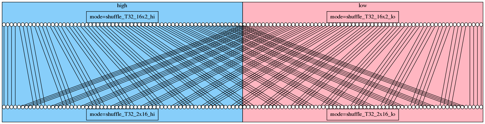
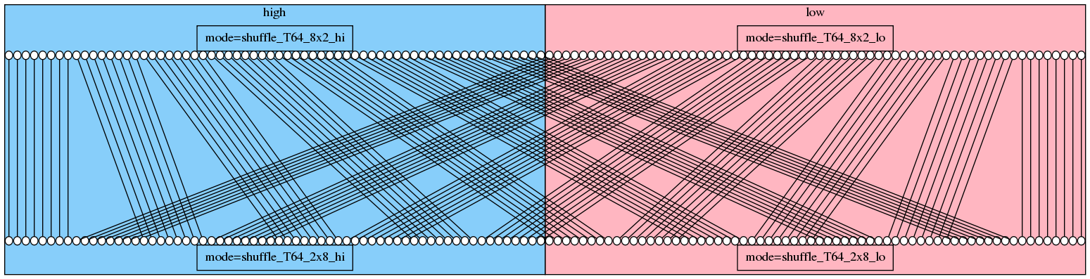
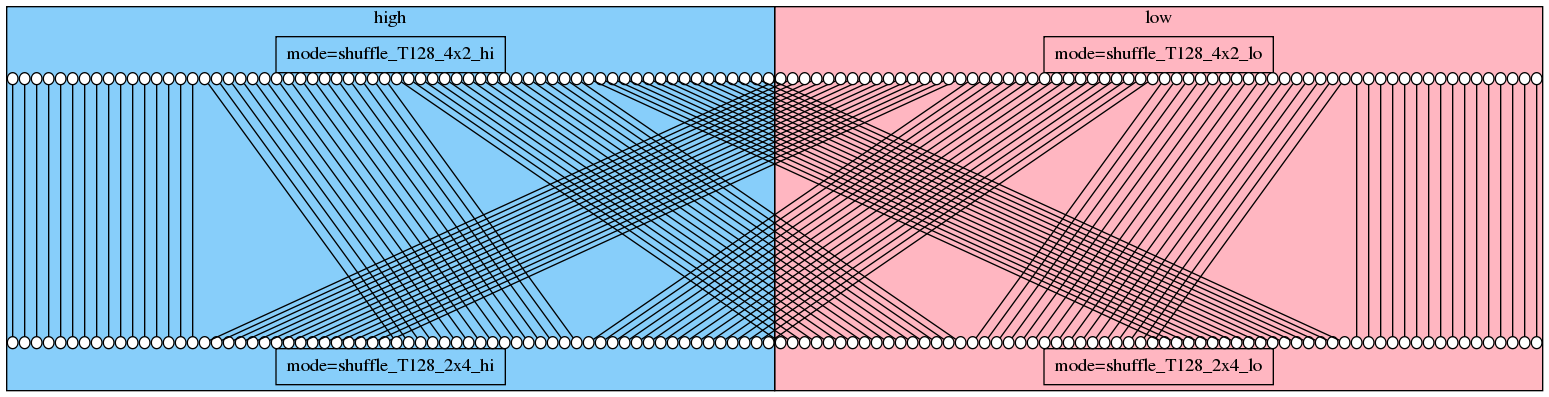
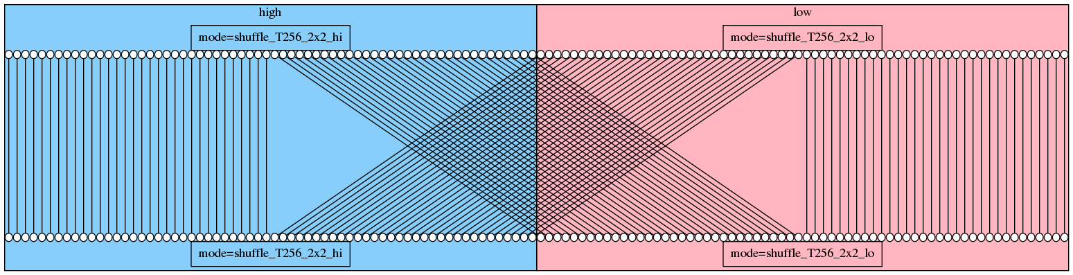
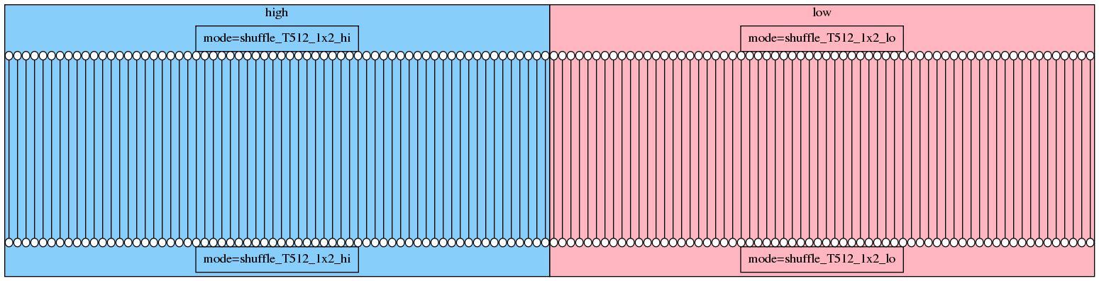
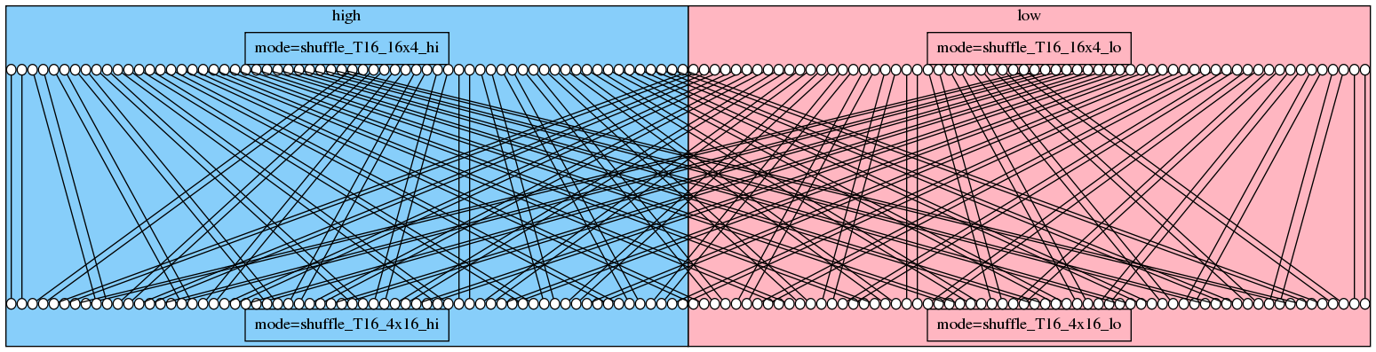
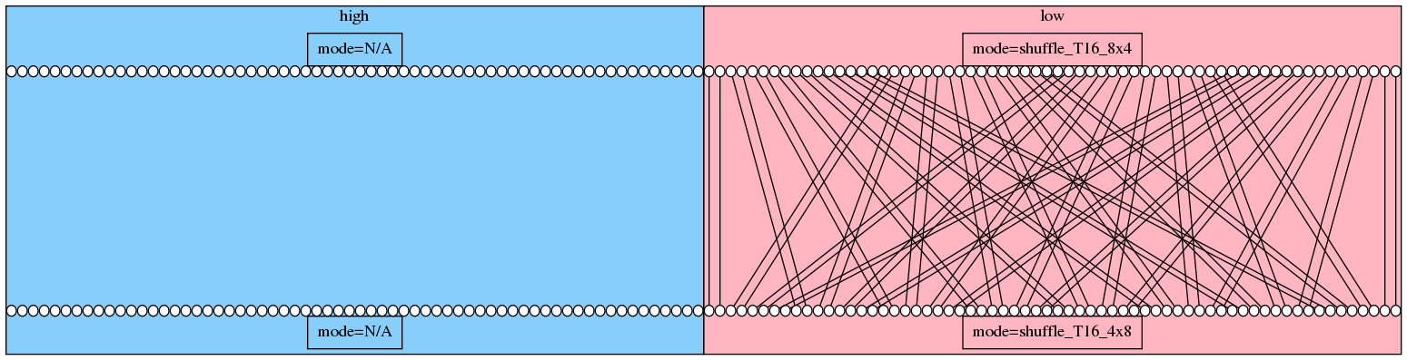
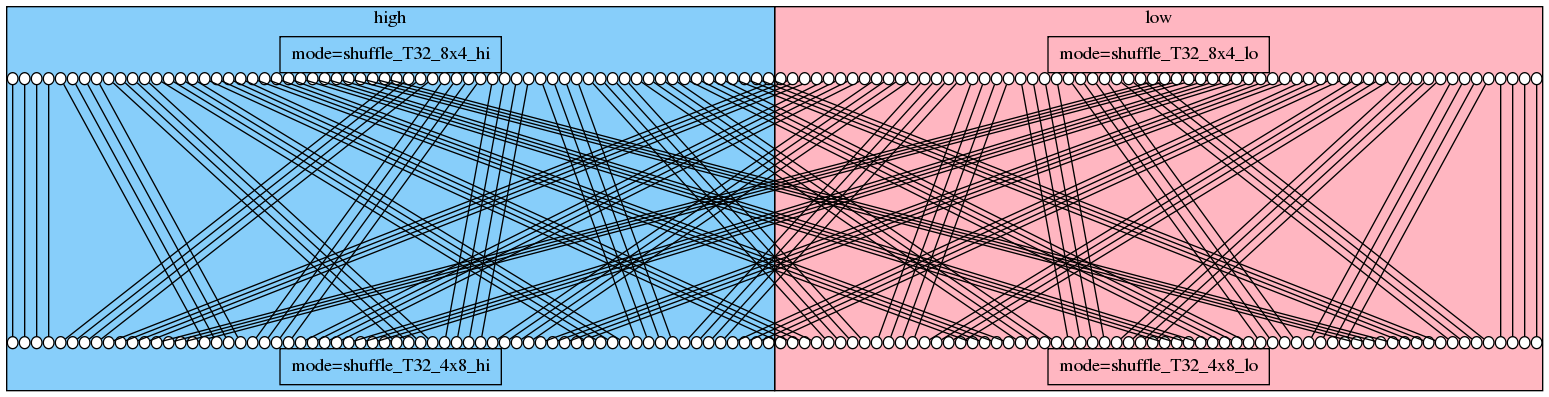
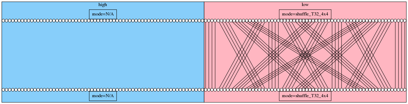
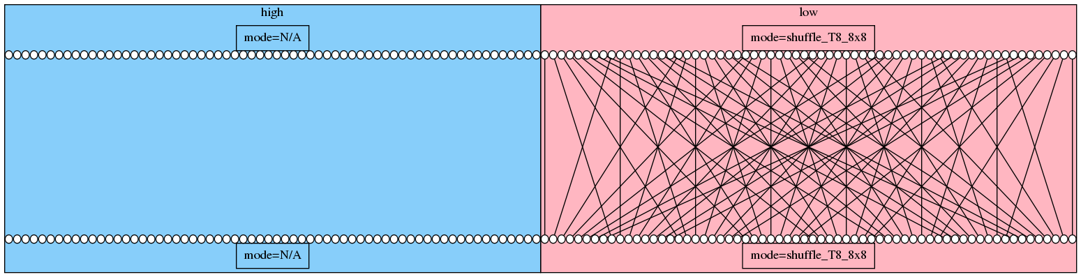
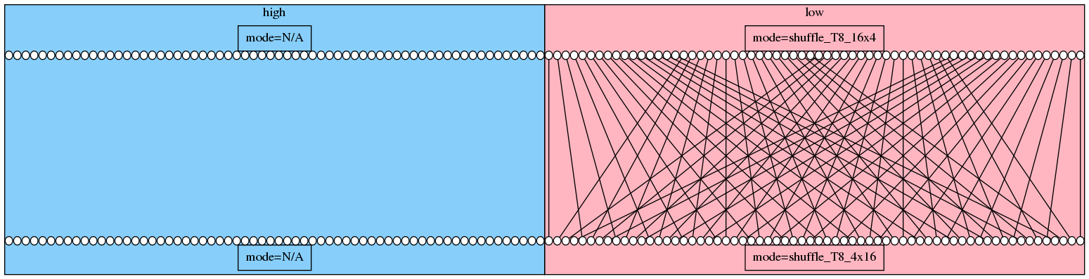
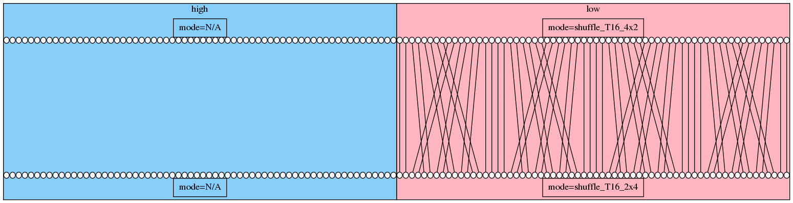
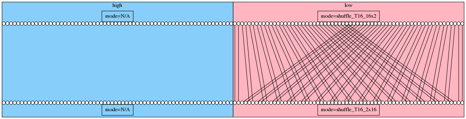
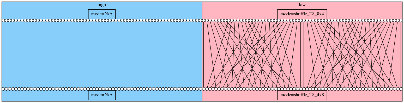
The following images illustrate the behavior of the shuffle modes. Each output is identified by a mode label. Every circle in the figure corresponds to one byte. The input is shown on the opposite side. The two input registers are concatenated and the output is produced depending on the selected mode. Differents modes are used to access the low or high 512 bits of the output. Some modes do not produce more matrices that require more than 512 bit. In those cases the second input register is not accessed.
A special mode is shuffle_T16_1x2_flip. This one does not transpose the matrix, instead it flips the inner dimension. This means that the order of values along the dimension is reversed. Since the inner dimension of this mode has exactly two values of 16 bits, this is the same as swapping each neighouring 16 bit values.