Task-level parallelism and pipelining in HLS (fork-join and beyond)
Creating parallel hardware with portable C code
Overview
Extracting task-level hardware parallelism is key to designing efficient C-based IPs and kernels. In this article, we focus on the Xilinx high-level synthesis (HLS) compiler to understand how it can implement parallelism from untimed C code without requiring special libraries or classes. Being able to combine task-level parallelism and pipelining with addressable memories or FIFOs is a prominent feature of the Xilinx HLS compiler. After an overview of various overlapping execution modes that can be obtained, this article focuses on the simplest case: how fork-join parallelism, and more generally the parallelism in a DAG (directed acyclic graph) of tasks, combined with the use of ping-pong buffers, enables a form of handshake-based task-level (i.e., coarse-grain) software pipelining.
Parallel and overlapping execution
Among the many factors that are at play to enable concurrency of execution in HLS, some would impede acceleration, e.g., the sharing of computing resources between tasks, or the reliance on storage resources with a limited amount of physical ports. Still, the potential for parallelism and overlapping execution exists in many algorithms and the fine grain nature of the Xilinx device logic fabric enables these scenarios and can realize them with various degrees of concurrent execution.
It should be noted that when functions have no dependencies at all induced by the variables they process (i.e., truly unrelated tasks), they can also be implemented as separate HLS projects. In fact, the divide-and-conquer approach can be considered up-front: Xilinx compute acceleration tools would then connect these independent kernels to the rest of the platform or the user could connect these HLS IPs manually in Vivado IP Integrator in the context of a hardware flow.
But let us focus here on kernel design itself, with possible inter-task dependencies.
Often, compute tasks invoked one after another in the C code implement a “recipe”, i.e., one function produces data that the next one consumes and so forth. In this common producer-consumer scenario, tasks cannot be executed in parallel since data need to be ready before further processing can take place. Are we then forced into a linear model of execution? Fear not! A tool like HLS can, under some restrictions, assess the relations between data accesses (producer-consumer relations) and define a task graph on which parallelism and pipelining can be exploited.
The following diagrams illustrate different overlapping executions for the simple example of 4 consecutive tasks (i.e., C/C++ functions) A, B, C, and D, where A produces data for B and C, in two different arrays, and D consumes data from two different arrays produced by B and C. Let us assume that this “diamond” communication pattern is to be run twice (two invocations), and that these two runs are independent.
A fully-sequential execution corresponds to the diagram in Fig. 1 where the circles represent some form of synchronization used to implement the serialization.

Fig. 1: Sequential execution (two runs)
In the diamond example, B and C are fully-independent: they do not communicate, they do not access a shared memory resource, and if no sharing of computation resource is required, one can thus expect them to execute in parallel. This leads to the diagram in Fig. 2, with a form of fork-join parallelism within a run: B and C are executed in parallel after A ends, D waits for both B and C, but the next run is still serialized.

Fig. 2: Task parallelism within a run
Such an execution can be summarized as (A; (B || C); D); (A; (B || C); D) where “;” represents serialization and “||” represents full parallelism. This form of nested fork-join parallelism corresponds to a subclass of dependent tasks, namely series-parallel task graphs. More generally, any DAG (directed acyclic graph) of dependent tasks can be implemented with separate fork-and-join-type synchronizations.
Let us go a bit further. So far, the previous execution pattern exploited task-level parallelism within an invocation. What about overlapping successive runs? If they are truly independent, but if each function (i.e., A, B, C, or D) reuses the same computation hardware as for its previous run, we may still want to execute, for example, the second invocation of A in parallel with the first invocations of B and C. This is a form of task-level pipelining across invocations, leading to a diagram as depicted in Fig. 3. The throughput is now improved, because it is limited by the maximum latency among all tasks, rather than by the sum of their latencies. The latency of each run is unchanged but the overall latency for multiple runs is reduced.
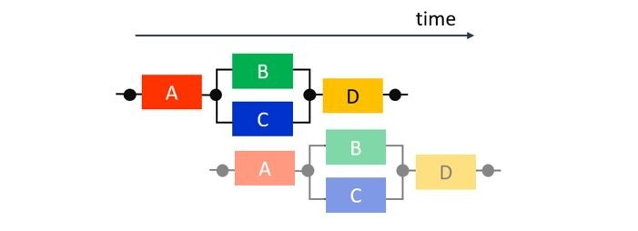
Fig. 3: Task parallelism within a run and pipelining across runs
Now however, when the first run of B reads from the memory where A placed its first production, the second run of A is possibly already writing in the same memory. To avoid overwriting the data before it is consumed, one can rely on a form of memory expansion, namely ping-pong memories (see hereafter).
Let us go even further. An efficient technique to improve throughput and reuse computational resources is to pipeline operators, loops, or functions. If each task can now overlap with itself, we can achieve simultaneously task parallelism within a run, task pipelining across runs, and pipelining within tasks, as shown in Fig. 4. The overall throughput of a run is further improved, because it now depends on the minimum throughput among the tasks, rather than their maximum latency.
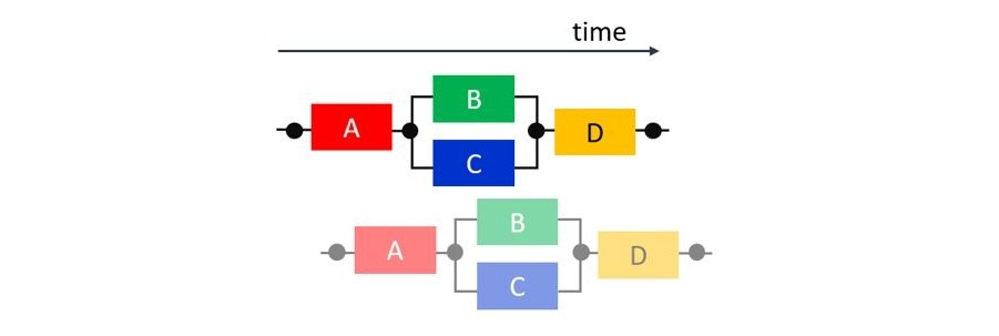
Fig. 4: Task parallelism within a run, pipelining of runs, and pipelining within a task
Finally, depending on how the communicated data are synchronized, only after all are produced or in a more element-wise manner, some additional overlapping within a run can be expected. For example, in Fig. 5, both B and C start earlier and are executed in a pipelined fashion with respect to A, while D is assumed to still have to wait for the completion of B and C. This last type of overlap within a run can be achieved if A communicates to B and C through FIFO accesses (represented as lines without circles). Unlike all previous execution patterns, using FIFOs can lead to deadlocks, suboptimal FIFO sizing, implementation subtleties, semantic issues due to non-blocking accesses, etc., which are beyond the scope of this article.

Fig. 5: Task parallelism and pipelining within a run, pipelining of runs, and pipelining within a task
A fork-join parallelism example with ping-pong memories
The combinations of task-level parallelism and pipelining described in the previous section are triggered by the HLS dataflow pragma. This feature builds a network of tasks, called processes, communicating through channels. Specific guidelines and coding style (the so-called “dataflow canonical form”) are documented in the HLS user guide. The Xilinx HLS compiler emits warnings or even errors when these requirements are not fulfilled.
Let us now give a practical illustration of how the compiler implements overlapping executions such as those in Fig. 3 and Fig. 4, using the same “diamond” topology: Function A reads an input array vecIn of 100 elements and produces two arrays, one read by B, one read by C. Then B and C perform some intermediate computations and produce one array each, both read by D. Finally, D produces an output array vecOut of same number of elements. To get the behavior of Fig. 3 (task graph parallelism and overlapped execution across runs), we apply the HLS dataflow pragma on the function that contains the calls to A, B, C, and D. To ensure the most throughput within the tasks, we pipeline and partially unroll the loops in each subfunction with the HLS pipeline and HLS unroll pragmas. The unroll factor of 2 is chosen to schedule two accesses per cycle and exploit at best the dual-port memories assumed by HLS on external connection for C arrays, i.e., here the ports of the “diamond” top function.
After running HLS C synthesis, the solution log confirms that the compiler was able to identify the processes, i.e., the communicating tasks with single producer-single consumer channels:

Fig. 6: Confirmation by HLS that processes were identified
When a design uses dataflow, the Xilinx HLS GUI also provides a specific view depicting the extracted tasks and the connections between them, as shown in Fig. 7 below.
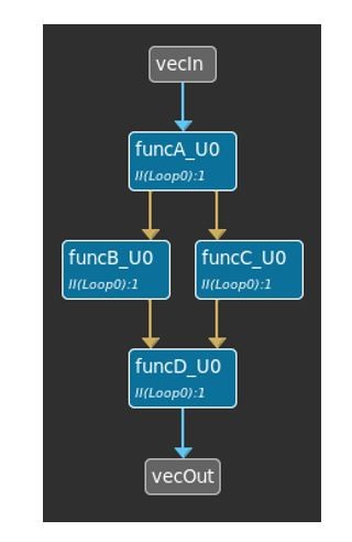
Fig. 7: Dataflow viewer
The code example in Fig. 8, with report excerpts comparing the results with and without dataflow, illustrate the differences in behavior and performances. Compared to the serial execution of Fig. 1, the use of dataflow leads naturally to an overlap execution as in Fig. 3, i.e., with both task parallelism (B and C) and pipelining across runs. However, by default, pipelined loops do not overlap their iterations across successive runs, they first fully flush before possibly be executed again. Thus, here, by default, the tasks do not overlap with themselves as they do in Fig. 4. Just as an illustration of such additional task pipelining, the code in Fig. 8 uses the HLS pipeline rewind feature (beyond the scope of this article), which allows tasks to start again a new invocation before the previous one is finished.
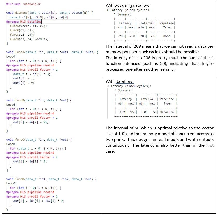
Fig. 8: Code example and summary of latency and throughput performances with and without dataflow
To further inspect the effect of dataflow, it is possible, during the HLS RTL/C co-simulation (CoSim), to select “wave debug”, Verilog, and the Xilinx simulator. The tool will then create specific dataflow waveforms to review. For our example, they look like this:
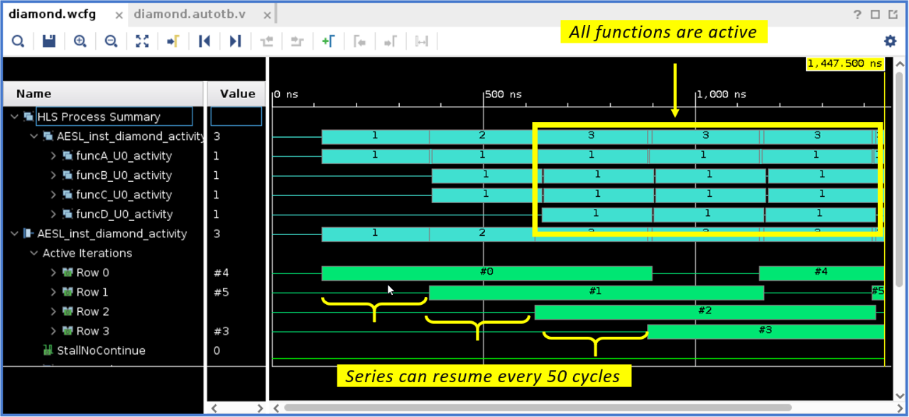
Fig. 9: Dataflow specific waveforms in Vivado simulator (launched from HLS)
As depicted in the “HLS Process Summary” upper section with cyan horizontal bars, initially only funcA is active, then funcB and funcC, then all are active. The “Active Iteration” lower section with green horizontal bars shows the 3 iterations coded in the testbench, each separated by about 50 clock cycles as expected.
To make such a task-level pipelining possible, when HLS implements dataflow, it interfaces the producer and the consumer with a “channel” made of two (the default value, which can be customized) buffers alongside their control logic. Every other invocation, the producer process generates data in a different buffer and the consumer process uses the buffer from the previous invocation. Some synchronization mechanisms implement the switching role of the two buffers, ensuring that the consumer can start only once its input buffer is ready and that the producer cannot overwrite a buffer not consumed yet. Such buffers are called ping-pong buffers (or PIPOs for short). In effect, they induce a memory duplication. It is possible to review how HLS implemented these resources in the “Memory” section of the report:
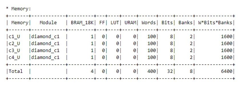
Fig. 10: Memory section of the synthesis report
Fig. 10 shows that 4 BRAMs were used, each channel uses 2 banks within a single dual-port BRAM. In this case we have 8-bits (char) x 100 (elements) x 2 (ping-pong) = 1600 bits, for a total of 6400 bits. For small PIPO buffers, HLS might use distributed RAM, which does not use dedicated blocks on the chip but rather LUTs. For large buffers, Vivado will connect several blocks of RAM together.
It should be noted that, in this default form of HLS dataflow (i.e., with PIPOs only, as depicted in Fig. 3 and Fig. 4), successive communicating tasks in a kernel run do not overlap: B and C can only start once their buffer from A (ping or pong) is released. As previously mentioned, B and C could possibly start earlier, as shown in Fig. 5, if FIFOs are used as an alternative approach to ping-pong buffers, when the data are consumed in the same order in which they are produced. This will be covered in a subsequent article.
Conclusion
In this quick overview of HLS hardware synthesis, we discussed the main forms of hardware parallelism and overlapped execution. These forms can be realized automatically with the Xilinx HLS pipeline and dataflow features. The latter in its simplest form creates and manages on-chip memory channels to move data between tasks. These data exchanges between producer and consumer are handled by the tool, no special classes or libraries are necessary.

About Frédéric Rivoallon
Frédéric Rivoallon is a member of the software marketing team in San Jose, CA and is the product manager for AMD HLS, besides high-level synthesis Frédéric also has expertise in compute acceleration with AMD devices, RTL synthesis, and timing closure. Past experiences taught him video compression and board design.

About Alain Darte
Alain Darte is a member of the AMD HLS compiler team, with expertise in both software and hardware acceleration. Previously an academic researcher, he worked on automatic parallelization, parallel computing, high-level code transformations, front-end and back-end code optimizations, static single assignment.